
Mold Design &
Manufacturing
From your drawing to production-ready steel tooling — DFM analysis, cavity machining, T1 trials, and lifelong mold support, all under one roof in Zhangzhou.
The Mold Is Where
Everything Starts
Injection molding quality is determined largely before a single shot is ever made — it's determined in the mold. A well-engineered mold with consistent cooling, balanced runner systems, and correct venting produces good parts reliably. A poor mold produces problems that no process tweak can fully correct.
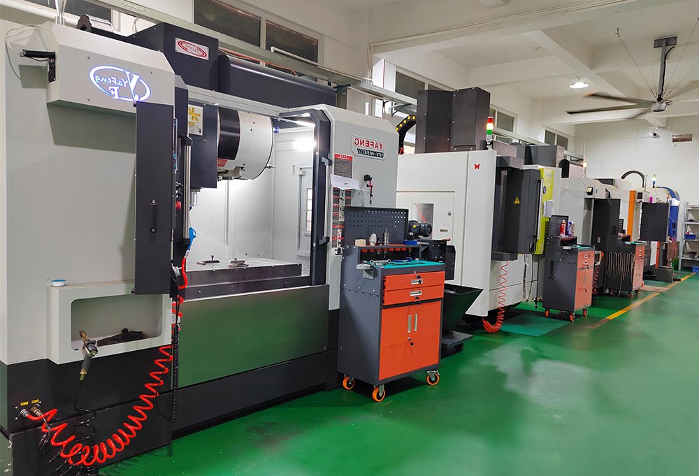
At XJHMFG, our mold-making workshop operates inside our injection molding facility. The same engineers who design your mold also oversee its trial on our production machines. This tight integration eliminates the communication gap that typically exists between a separate mold shop and a production facility — and it means we catch and fix issues in days, not weeks.
We handle every stage in-house: DFM analysis, mold design, CNC cavity machining, EDM and wire-cutting, polishing, mold assembly, and T1 trialing — without any step leaving our building.
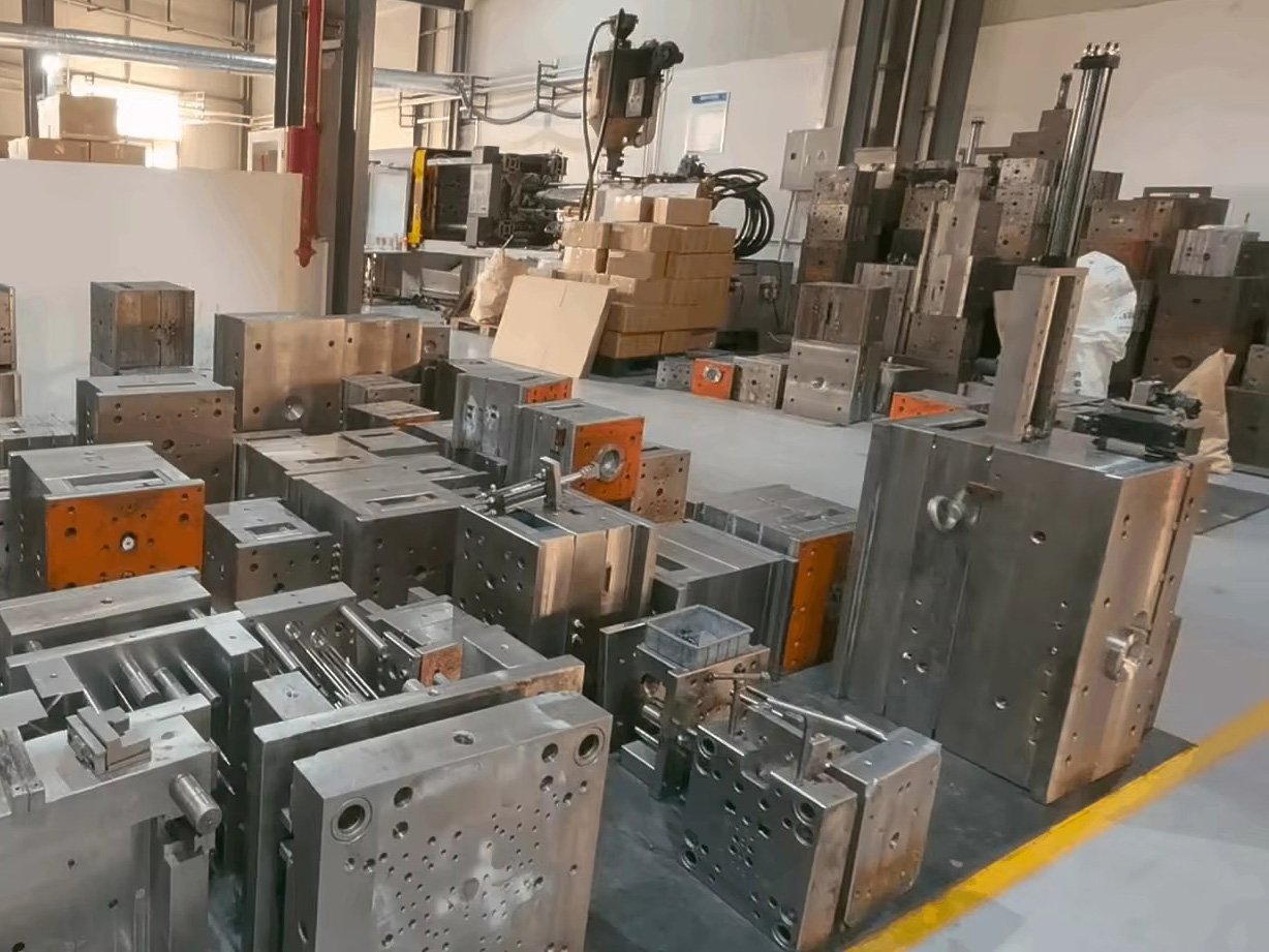
Mold Types We Design & Build
The right mold configuration depends on your production volume, part geometry, and timeline. We recommend the optimal solution during DFM review.
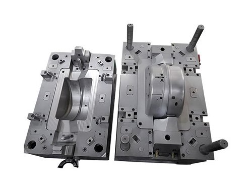
One part produced per injection cycle. Lowest tooling cost, fastest T1 timeline. Ideal for low-to-mid volume, large parts, or first-time molds needing flexibility for design changes.
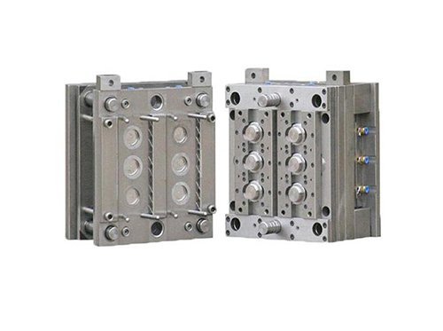
Multiple identical cavities produce 2, 4, 8 or more parts per cycle. Dramatically reduces unit cost for high-volume programs. Balanced runners ensure consistent filling across all cavities.
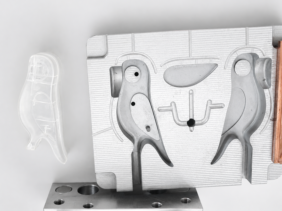
Multiple different parts (e.g. left/right halves of an assembly) produced in one mold in a single shot. Reduces tooling cost for assemblies. Requires careful runner balancing to ensure fill consistency.
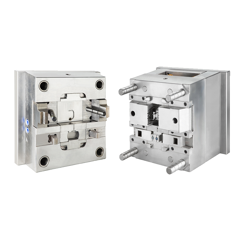
For parts with undercuts, side holes, or features that can't be formed by a straight pull. Sliders and lifters retract sideways during ejection to release the part without damage.
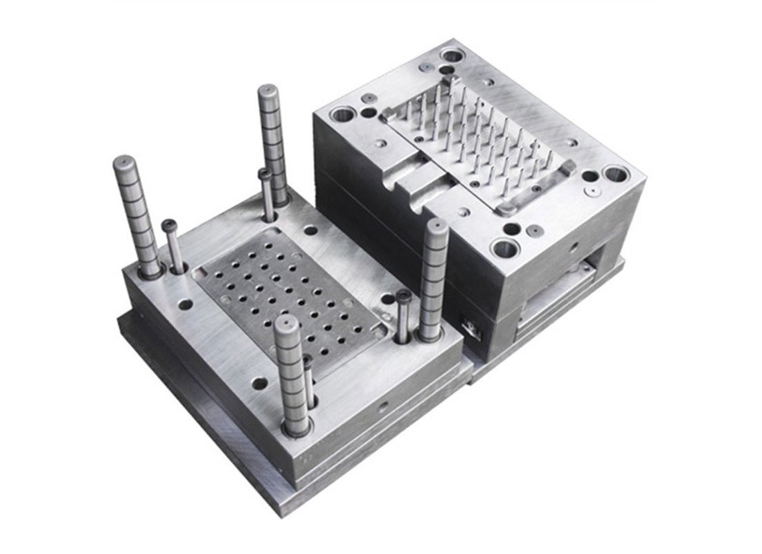
Heated manifold keeps the runner material molten, eliminating runner scrap between cycles. Ideal for high-volume programs with expensive resins or tight color requirements. Lower long-term material cost.
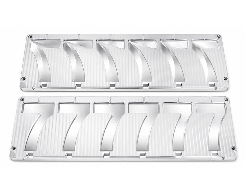
Soft aluminum or P20 steel tooling machined quickly for design validation or low-volume bridge production. Shorter lead time and lower cost than full production tooling — ideal before committing to a full mold.
6-Phase Mold
Manufacturing Process
Every mold we build goes through a structured, documented process — so nothing is left to guesswork and you always know where your project stands.
Mold Design Engineering — What We Actually Do
For buyers who want to understand the engineering behind their tooling — each topic below explains a critical element of mold design and how we approach it.
DFM (Design for Manufacturability) is an engineering review of your part before any steel is cut. Catching issues at this stage costs nothing; catching them after the mold is built costs money and time.
Key checks we perform:
| Wall Thickness | Uniform 1.5–4mm typical; thin walls cause short shots, thick walls cause sink marks |
| Draft Angles | Minimum 0.5–1° per side required for clean ejection; textured surfaces need 2–3° |
| Undercuts | Features that prevent straight pull — require side actions or lifters (adds cost and lead time) |
| Gate Location | Where plastic enters the mold — affects weld lines, fill balance, and surface appearance |
| Weld Lines | Where two flow fronts meet — potential weak point; gate position can relocate them |
| Sink Marks | Depressions caused by thick sections; geometry or rib design adjustments resolve them |
| Parting Line | Where cavity and core separate — must be placed to minimize visibility and ease ejection |
Cooling accounts for 60–70% of injection molding cycle time. An optimized cooling system doesn't just make production faster — it controls part warpage, dimensional stability, and surface finish consistency.
We design conformal cooling channels that run as close to the cavity surface as feasible, maintaining uniform mold temperature and minimizing hot spots. For complex geometry, we may use baffles, bubblers, or heat pipes to reach areas conventional drilling can't.
| Cooling Channel Diameter | 8–12mm typical, positioned 1.5× diameter from cavity surface |
| Coolant | Water at 20–40°C (controlled by our chillers) |
| Mold Temperature Range | 20–80°C depending on material (PC requires warmer molds) |
| Cycle Time Impact | Proper cooling typically reduces cycle time by 15–30% vs poorly cooled molds |
The runner system carries molten plastic from the injection point to each cavity. The gate is where it enters the cavity. Both significantly affect part quality, cycle time, and material waste.
Cold Runner: Plastic solidifies in the runner channels and must be removed as a sprue with each cycle. Lower tooling cost, easier maintenance. The runner can be recycled (regrind), but adds material usage.
Hot Runner: Heated manifold keeps material molten — no runner waste, shorter cycle, better fill balance. Higher tooling cost but lower long-term material cost for large volumes.
| Gate Types We Use | Pin gate, fan gate, submarine gate, edge gate, valve gate (hot runner) |
| Gate Location | Chosen to minimize weld lines, control fill, and hide gate vestige |
| Hot Runner System | Available for orders of 100,000+ pcs; ROI typically within 2–3 production runs |
After the part cools, it must be ejected cleanly without deformation, whitening, or surface damage. Ejection system design depends on part geometry, wall thickness, draft angles, and material stiffness.
Ejector pin systems are the most common — multiple pins push the part off the core simultaneously. We position pins carefully to avoid visible witness marks on cosmetic surfaces and ensure force is distributed evenly.
For thin-wall or soft-material parts, we may use stripper plates, air-assist ejection, or sleeve ejectors to avoid pin marks. For deeply textured surfaces, delayed ejection sequences allow the part to cool further before release.
| Standard Ejectors | Round pins, blade pins, sleeve ejectors |
| Pin Diameter | 2–16mm depending on load requirements |
| Ejector Stroke | Calculated based on part height + 5–10mm safety margin |
| Return System | Springs or hydraulic return; timed to mold close for safety |
As plastic fills the mold cavity, it displaces air. If that air has nowhere to go, it compresses — creating burn marks, short shots, and high injection pressure that strains the machine and reduces tool life.
We place venting channels (typically 0.01–0.03mm deep, 5–10mm wide) at the parting line, at the end of fill, and along ejector pins. For complex multi-cavity or hot runner molds, venting design is especially critical to ensure consistent fill across all cavities.
Proper venting is one of the most common things we correct during DFM review — it's not visible in the final design but has an outsized impact on part quality and production efficiency.
| Vent Depth | 0.01–0.03mm (deep enough to allow air, shallow enough to prevent flash) |
| Vent Width | 5–10mm, placed every 25mm around parting line |
| Vent Locations | End-of-fill, last-to-fill areas, corners, and behind ejector pins |
Mold Steel Grade Reference
The steel grade determines your mold's lifespan, surface finish capability, and corrosion resistance. We recommend the right grade during DFM review based on your volume and material.
Mold QC Checkpoints
Quality checks happen at every stage of mold manufacturing — not just at T1 trial. By the time samples reach you, the mold has already been verified at multiple levels.
Mill certificate verified against order; hardness spot-checked before machining begins. Wrong steel grade = unacceptable — caught before a single cut.
After CNC finishing, critical cavity dimensions checked against mold drawing using CMM and precision gauges. Any deviation corrected before EDM or assembly.
Mold opens, closes, and ejects smoothly by hand before going on the press. Cooling water circuits pressure-tested for leaks. Ejector travel measured.
First-shot samples dimensionally measured against part drawing. Surface finish, flash, sink, and short shot assessed. Results documented and shared with buyer alongside samples.
Which Mold Type
Is Right for You?
Use this comparison to shortlist your tooling type before our DFM review — we'll confirm and refine the recommendation based on your exact part.
| Factor | Single Cavity | Multi-Cavity | Family Mold | Hot Runner | Rapid Tool |
|---|---|---|---|---|---|
| Tooling Cost | Lowest | Higher | Medium | Premium | Low |
| Unit Cost (high volume) | Higher | Lowest | Low | Lowest | Higher |
| T1 Lead Time | Fastest | Standard | Standard | Longer | Fastest |
| Design Change Flexibility | ✓✓ High | Medium | Medium | Low | ✓✓ High |
| Runner Waste | Yes (cold) | Yes (cold) | Yes (cold) | Zero | Yes |
| Ideal Production Volume | 500–50K | 50K+ | 5K–100K | 100K+ | 50–5K |
| Complex Geometry Support | ✓ | ✓ | — | ✓ | Limited |
Ready to Start Your Mold Project?
Send your drawing, sample, or idea — free DFM review and mold quote within 24 hours. No commitment required.