
Secondary Machining for Injection Molded Plastic Parts: 12 Precision Processes Explained
Meta description: A technical guide to the 12 most common secondary (post-molding) machining operations for plastic parts — tapping, counterboring, side-hole drilling, R-corner rounding, 3D contour machining and more.
Why Injection Molding Alone Isn’t Always Enough
Injection molding is efficient at reproducing a fixed geometry thousands of times, but it isn’t the right tool for every feature on a plastic part. Fine threads, undercut side holes, tight-tolerance counterbores, or a one-off prototype geometry are often faster, cheaper, or simply more accurate to add after the part comes off the press — using CNC secondary machining rather than building the feature into the mold itself.
This is especially true in three common situations:
- Prototyping and low-volume runs, where cutting a full production mold with every micro-feature isn’t yet justified.
- Threaded or high-tolerance features that wear mold steel faster than the rest of the cavity, or that are difficult to mold without slides and lifters.
- Custom, one-off, or reverse-engineered parts produced directly from a customer’s drawing or physical sample, with no mold involved at all.
Below is a technical breakdown of the twelve secondary machining processes most frequently requested on plastic components, what each one is used for, and what to specify when you request a quote.
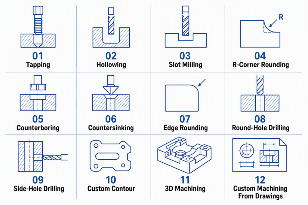
1. Tapping
Thread tapping cuts internal threads directly into a plastic boss or a pre-drilled pilot hole, producing a functional threaded fastening point without a metal insert.
Typical use: Mounting screws, adjustable fittings, assembly points on enclosures and brackets.
Spec to provide: Thread standard and size (e.g., M3×0.5, UNC 4-40), thread depth, and target material — some resins require a slightly oversized pilot hole to avoid thread stripping under repeated assembly.
2. Hollowing / Through-Cutouts
Hollowing removes solid material from a molded blank to create open windows, ventilation cutouts, or weight-reduction pockets that would be difficult or impossible to mold directly due to mold-release or core-pull limitations.
Typical use: Speaker grilles, ventilation panels, lightweight structural brackets.
Spec to provide: Cutout geometry (DXF/STEP), wall thickness remaining around the cutout, and edge finish requirement.
3. Slot Milling
Slot milling cuts precision channels or grooves into a flat or curved surface — for cable routing, gasket seating, or sliding-fit mechanisms.
Typical use: O-ring/gasket grooves, cable management channels, linear guide slots.
Spec to provide: Slot width, depth, and tolerance class; whether the slot needs a flat or radiused bottom.
4. R-Corner Rounding / Fillet Machining
This process machines a rounded radius onto a sharp external or internal corner, reducing stress concentration and improving both handling safety and cosmetic appearance.
Typical use: Enclosure edges, ergonomic handles, structural ribs prone to stress cracking.
Spec to provide: Radius value (e.g., R2, R5), and whether the radius is cosmetic only or load-bearing.
5. Counterboring / Spot-Facing
Counterboring machines a flat-bottomed, stepped recess around a hole so that a screw head, washer, or bearing seats flush with — or below — the surrounding surface.
Typical use: Flush-mount screw assembly, recessed fastener heads on cosmetic surfaces.
Spec to provide: Counterbore diameter and depth, paired fastener head dimensions.
6. Countersinking / Flared-Hole Machining
Unlike a counterbore’s flat step, a countersink cuts a conical taper into a hole so a flat- or oval-head screw sits flush with the surface — commonly required where a raised screw head would interfere with an assembly or a moving part.
Typical use: Flush-fastening on outer housings, panels that mate against another flat surface.
Spec to provide: Countersink angle (typically 82° or 90°) and screw head profile.
7. Edge Deburring & Rounding
This finishing pass removes sharp burrs and flash left from molding or machining, and lightly rounds exposed edges for a safer, cleaner finish — often a required step before a part ships, regardless of whether other secondary machining was performed.
Typical use: Any part with a hand-contact surface; a standard finishing step on export-quality parts.
Spec to provide: Edge-break size (e.g., 0.2–0.5mm), and whether a full radius or a light chamfer is preferred.
8. Round-Hole Drilling
Standard through- or blind-hole drilling adds mounting holes, cable pass-throughs, or pilot holes for later tapping, at diameters and positions not included in the original mold.
Typical use: Late-stage design changes, mounting hole additions, pilot holes ahead of tapping.
Spec to provide: Hole diameter, depth (through or blind), and positional tolerance.
9. Side-Hole Drilling / Cross-Drilling
Side or cross-drilling machines a hole perpendicular to the part’s primary draw direction — a feature that would otherwise require a side-action slide in the mold. Producing it as a secondary operation is often more economical for prototypes and low-to-mid volumes.
Typical use: Cross-pin holes, side-entry cable ports, perpendicular fastening points.
Spec to provide: Hole axis direction relative to the part’s datum, diameter, and depth.
10. Custom / Irregular Contour Machining
This covers non-standard, irregular geometries that don’t fit a simple hole, slot, or radius category — typically machined to match a customer sketch, reference part, or freeform design requirement.
Typical use: Branding cutouts, custom mechanical interfaces, one-off design features.
Spec to provide: A dimensioned drawing or 3D file; a physical reference sample if no digital file exists.
11. 3D Contour Machining
Full 3D machining uses multi-axis CNC toolpaths to cut complex curved or freeform surfaces directly from a solid block or a molded blank — used when a shape is too intricate for standard 2.5-axis milling or drilling operations.
Typical use: Sculpted enclosures, ergonomic grips, complex functional prototypes.
Spec to provide: A complete 3D model (STEP/IGES) and the surface finish requirement.
12. Custom Machining From Drawings & Samples
For parts with no existing digital file, this service reverse-engineers a physical sample — or interprets a hand-marked drawing — into a machinable specification, producing a matching part without requiring the customer to generate CAD data themselves.
Typical use: Replacement parts, legacy components, early-stage concepts without formal drawings.
Spec to provide: The physical sample and/or drawing, plus any known material or dimensional requirements.
Choosing Between Mold-In Features and Secondary Machining
As a general rule:
| Factor | Favors Molding the Feature In | Favors Secondary Machining |
|---|---|---|
| Production volume | High volume (10,000+ pcs) | Prototype / low-to-mid volume |
| Feature complexity | Simple, straight-pull geometry | Undercuts, side holes, fine threads |
| Tolerance requirement | Standard molding tolerance | Tight tolerance (±0.05mm or better) |
| Design maturity | Finalized, stable design | Still in validation / early production |
Most production parts ultimately use a mix of both — core geometry molded in, with tapping, counterboring, and edge finishing added as a secondary pass. Specifying this correctly at the quoting stage avoids unnecessary tooling cost for features that can be machined faster and cheaper after the fact.
Getting a Quote
When requesting a quote for any of the processes above, providing a dimensioned drawing or 3D file — plus the target quantity and material — allows for the most accurate turnaround and pricing estimate. For features without an existing file, a physical reference sample and a written description of critical dimensions is normally sufficient to begin.
Keywords: secondary machining injection molded parts, CNC post-molding machining, plastic parts tapping and counterboring, custom CNC machining from drawing, side hole drilling plastic parts, R-corner rounding plastic components, 3D contour machining plastic prototype, precision plastic parts finishing services